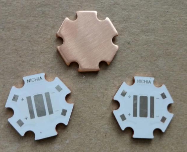
Metal Core PCB Surface Mounting Components
A key factor in incorporating MCPCB design is the use of surface mounted components instead of any plated through holes. The reason is that the bottom of the layer structure is thick metal sheet, so plated through holes (or non-plated holes with conductive element leads inserted into them) will lead to short circuit.

Most LED PCBs built on multi-layer (2 +) FR4 substrates must use closely spaced through-hole patterns under each component to transmit heat. If the solder is not filled, the solder will migrate through these holes during assembly, resulting in imperfect solder joints.
For metal core PCB, the work of hole passing is done by the material itself. The whole bottom is made of metal, which has more efficient thermal conductivity, so the cooling is strengthened and no heat dissipation is needed through the hole. As a result, most MCPCBs require the least drilling – usually only a few large mounting holes.
By eliminating the ability to drill through holes and stack multiple panels while drilling large holes, manufacturers can quickly move your circuit boards through frequent bottleneck operations in PCB facilities. Then, after a short drilling cycle, your layer 1 MCPCB bypasses the preparation steps of the electroless copper deposit (or graphite) hole wall required for PTH processing and directly performs circuit imaging. From then on, your metal core PCB will follow the same process steps as any standard FR4 design, more or less.
Considerations for metal core PCB manufacturer
MCPCB manufacturing has some processing considerations, but as long as you understand how the material works and maintain the design as a single-layer SMT, then the design of your PCB should not be very different from any other single-chip PCB, multi-layer PCB. If you find it impossible to route your design to a single layer, please note that other MCPCB configurations are also possible, including a two-layer PTH board with aluminium inside (which requires expensive pre-drilling/filling insulation/re-drilling steps to form through-plated holes that do not short circuit). Two or more layers are fabricated according to standard PCB process, but FR4 is replaced by thermal dielectric material, and the metal backplane is laminated to the bottom for heat transfer.
MCPCB may be an excellent solution when the design gives priority to cooling multiple LEDs. They are becoming more and more common in various lighting applications – for homes, workplaces and vehicles. Although they are subject to certain design constraints, the manufacturing process is different from most other PCBs and, to some extent, simpler.