In today’s world of modern technologies, we see high tech PCBA 2devices all around us, from our houses to our offices, workplaces, roads, marketplaces, education institutions everywhere we see modernization of technology and key to all these technologies is advancement in Electronics Industry.
Day by day, scientist and engineers and working on advancements in micro-electronics, semiconductors, nanotechnology, communication engineering and many more. In this article we will specifically focus on core electronics hardware and discuss about the electronic components, circuit boards and component selection and assembly of the electronic components on PCB.
What is PCB Board:
A circuit board also known as
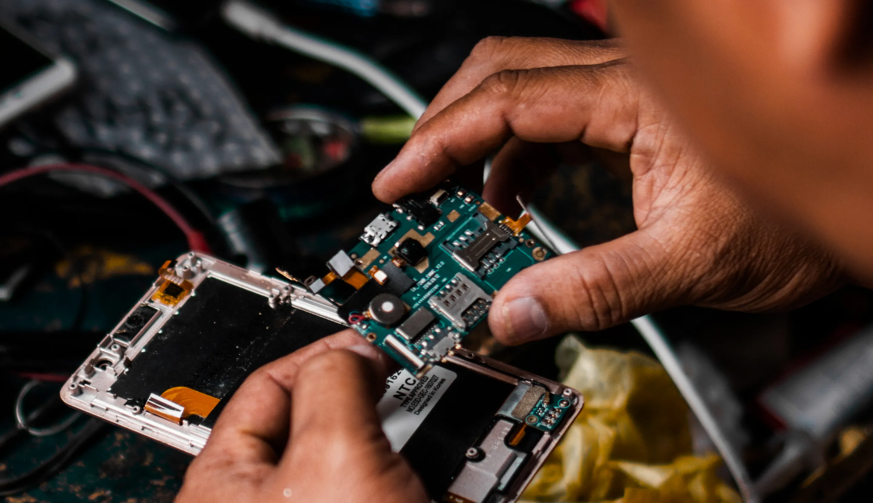
PCB (Printed Circuit Board) is platform made of silkscreen, solder mask, copper, and substrate. The substrate is FR-4 composite material made of woven fiber glass cloth with an epoxy resin binder which is fire retardant that is why named FR (Fire Retardant).
The components solder upon PCB to make it function as electronic device. The assembly is known as PCB Assembly or PCBA. The PCB is designed in a particular CAD software like ALTIUM, ORCAD, EAGLE etc. These software can generate the circuit design (Schematics) and then circuit designer can then layout PCB in this CAD software. This software then generates “GERBER” file that can be fed into PCB fabrication machines to actually print tracks and fabricate PCB.
Electronic Devices and Equipment:
There are various electronic devices and equipment that contains electronic components. Some of them are Linear Power Supplies, Switch Mode Power Supply, Amplifier, Filters, Oscillators, Oscilloscope, Function Generator, Digital Multi-Meter, Network Analyzers, Spectrum Analyzers etc. These are the laboratory equipment that are used to develop other electronic products like consumer electronics , industrial electronics, automobile industry, Military and Defense products.
Applications of Electronic Devices:
Some of the consumer electronic products include LED TV, LCDs, Android Mobiles, Telephones, Wearable electronics, gadgets, etc. Industrial products like PLC, Relays, Switches, Sensors, Actuators, Servo Motor drives, DC motor conveyer belt electronics etc. Automobile electronics include car charger, AM/FM radio electronics, GPS tracker/navigator, LED lights controls, relays, valves, fuses etc.
The electronic circuit design is based on the requirements from the customer. There are two main categories of components. 1- Active Components and 2- Passive Components
The active components are those that need power source to operate like OPAMPs, transistor, MOSFETs etc while the passive components are those that dissipate energy like resistors, capacitors, inductors etc.
Electronic Components:
Example 1: (Relay Switch Circuit)
Here in this circuit, we have selected NPN type BJT transistor BC337. This transistor is connected in common emitter mode and 1K? resistor is the base resistor used to control the base current . The 10K? resistor is used to tie the Base of BC337 to ground (GND) so that when trigger at input positive edge trigger is given, then the transistor will go in saturation and conducts through Collector and Emitter to short the GND to Relay coil. Hence Coil will energize and Normally Close (NC) the contacts of Relay.
On the other hand if the trigger is not applied transistor will remain in cutoff and C-E junction will remain open and GND is not shorted to coil of relay hence relay will remain in Normally Open (NO)
Transistors:
The two main types of transistors are BJT and MOSFET. The BJT transistor is a current controlled device and is commonly used in relay control switches.
Relay:
The relay is an Electromechanical electronic components, that has a coil and two contacts (NO and NC). This coil when 12VDC is applied the relay will change its state from NC to NO and vice versa
The relay are available in 5V, 12V, 24VDC coils and contacts ampere ranging from 10A to 30 A. So if you have to drive heavy load like water pump, Air Conditioner, Blower, Large Servo Motors, then use high ampere relays otherwise for small loads like bulb, LED lights etc use small relays.
Resistors: SMD Resistor
The resistor is used to control the current flow and divide the voltage as required. In our case above, we have used “Voltage Divider Network” that drops the voltage at 1K? and pass remaining potential to 10K? to the base. The table to recognize and select the proper resistor is given. The resistors are very cheap and available at every electronic store. They are available in SMD and Through hole types.
Example 2: (Power Supply)
Here in this circuit, we have used adjustable LM317 voltage regulator. The voltage regulator can generate stable DC Voltage output programmed by the two resistors R1 and RV1. Capacitor C3 is the bypass capacitor to connect adjust pin to GND to improve ripple rejection capability. C1,C2,C4 used to eliminate ripple voltage. Diode D5 is used to protect reverse current from output to protect regulator IC.
D1,D2,D3,D4 are full bridge converter to convert AC to DC level. RV1 is trim pot used to set the fixed output voltage.
Transformer:
The transformer is the device that converts high AC voltage like 230VAC to 24VAC low voltage to be used by bridge rectifier. The transformer is selected by finding turns ratio according to the primary and secondary voltages.
Diode:
This is the semiconductor components, used in bridge rectifiers,fly-back / fly wheel purpose. This diode will forward bias and drop 0.7V across it. In semiconductor devices, Silicon is the important ingredient and proper doping will cause the barrier / junction creation.
Capacitor:
This passive component, is very common in electronics and used in dual and single power supplies. Main purpose is filtering. In timing circuits, it is used as RC timers. In OPAMP integrators used in feedback loop. The larger the rated voltage and capacitance, the larger the size of capacitor. If the output voltage is regulated at 24VDC then the output ripple capacitor should be selected at rated voltage greater than 24V like around 100V. Otherwise the capacitor will burst or swollen. The longer lead is positive and smaller lead is negative leg.
Voltage Regulator:
The linear voltage regulators are available under 1A rating and can provide output voltage 1.2V to 438V DC. The voltage regulator is selected to check the least dropout voltage, number of outputs, output voltage polarity, input voltage range and packaging as desired case to case basis.
Potentiometer:
The trim pot is widely used in various electronic circuits. It is used in voltage divider circuits, to set the reference voltage in OPAMP comparator circuits, to set the output voltage in adjustable voltage regulators, used in RF circuits for tuning, used in timers to set the value of R in RC timers. The code 102 written means that.
Soldering Electronic Components:
The most important tool in soldering the components is soldering iron itself. The tip of the iron is at 400oC and its tip can be replaced as required. Connect your iron to AC socket and wait till it gets hot enough. Then take a little soldering wire and touch at the tip, a smoke will raise indicating that iron is ready to solder. This little solder on the tip also helps the heat to flow from iron tip to joint. This process is called “tinning”
You must have a soldering iron stand, so you can place in it when not in use. Soldering should be done in place where there is ventilation. The smoke of solder wire is injurious to health
You should have a wet sponge so as to clean iron tip as required. Now as your iron is ready, grab it like a pen and touch the iron tip with both soldering wire and joint. The joint is the point where component lead and PCB track needs connection. Now hold the tip at the joint for 1-2 seconds until the solder is formed like a “mountain”. After 1-2 seconds the solder cools and you see mountainous like shiny solder. This soldering is good. While if you see like balls of solder then this is not good.
Soldering Precautions:
1- Some components are heat sensitive, so applying solder tip too long will damage the component like transistors
2- Some components are ESD (Electro Static Discharge) sensitive, so you have to earth your hands before touching or unpacking these components from their special ESD protective packing
What is Solder:
Conventional solder is alloy of tin and lead, 60% tin and 40% lead. Melting point 200°C. Modern solder is lead free and alloy of tin along other metals like copper and silver. Melting point 220°C. Covering a surface with solder is known as ‘tinning’ due to tin content of solder.
De-soldering:
A solder sucker is used to de-solder the components from board. Apply iron tip at the joint, now as the solder melts apply sucker to suck the molten solder. Copper braid is also good, it absorbs the molten solder into itself away from the joint. Apply heat from iron tip to the joint until solder melts then introduce copper braid to soak the molten solder and then remove the copper braid then iron tip.