PCB engineers refer to senior engineering and technical personnel engaged in research, teaching, product design, scientific and technological development, production and management of various electronic equipment and information systems. Generally divided into hardware engineers and software engineers.
Hardware Engineer: mainly responsible for circuit analysis and design; and
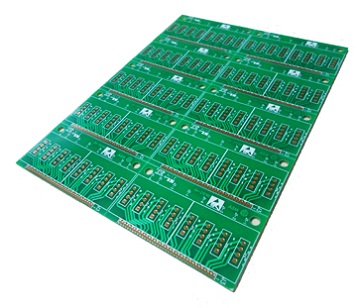
PCB layout design with computer software as a tool, testing and debugging after
PCB manufacturing and welding of electronic components in the factory;
Software Engineer: mainly responsible for MCU, DSP, arm, FPGA and other embedded programming and debugging. FPGA programs sometimes fall into the category of hardware engineers.
People make mistakes, not to mention engineers? Although time flies, PCB engineers often make the same mistake! Now, please take your seats according to the number and see if you have won the move.
1. It doesn’t matter how much resistance these pull up / pull down, so choose an integer of 5K.
Comments: there is no 5K resistance in the market, the closest is 4.99k (accuracy 1%), followed by 5.1k (accuracy 5%), and its cost is 4 times and 2 times higher than 4.7K with 20% accuracy. There are only 1, 1.5, 2.2, 3.3, 4.7 and 6.8 types of resistance values with 20% accuracy (including integral multiples of 10); similarly, there are only the above values for capacitance with 20% accuracy. If other values are selected, higher accuracy must be used, and the cost will be doubled, but it can not bring any benefits.
2. As long as the software is required for this part of the circuit, there will be no problem in the design
Comments: many electrical characteristics of hardware are directly controlled by software, but software is often unexpected, and it is impossible to predict what operation will be after the program flies. The designer should ensure that no matter what kind of operation the software does, the hardware should not be damaged permanently in a short time.
3. This logic can be built with 74xx gate circuit, but it’s too rustic. It’s better to use CPLD, which is much more high-grade
Comments: 74xx gate circuit only a few cents, and CPLD at least dozens of dollars. The cost has been increased by N times, but the work of production and documentation has been increased several times.
4. The PCB design requirements of this board are not high, so use a smaller line to automatically distribute it
Comments: automatic wiring is bound to take up more PCB area and produce many times more vias than manual wiring. In large quantities of products, the factors considered by PCB manufacturers to reduce price are not only commercial factors, but also the line width and the number of vias. They affect the product rate of PCB and the consumption of drill bits respectively, saving the cost of suppliers and finding the reason for price reduction ??
5. Our system is powered by 220 V, so we don’t have to worry about power consumption
Comments: low power design is not only to save power, but also to reduce the cost of power module and cooling system, and reduce the interference of electromagnetic radiation and thermal noise due to the reduction of current. As the temperature of the device decreases, the lifetime of the device will be prolonged accordingly (the life of the semiconductor device will be shortened by half for every 10 degree increase in the working temperature of the semiconductor device).
6. All of these bus signals are pulled with resistance, which makes you feel relieved
Comments: there are many reasons why signals need to be pulled up and down, but not all of them have to be pulled. If a simple input signal is pulled by a pull-up or pull-down resistor, the current will be less than tens of microamperes. However, if a driven signal is pulled up, the current will reach the level of Ma. In today’s system, the address is usually 32 bits, and there may be 244 / 245 isolated bus and other signals. If all the above-mentioned signals are pulled up, several watts of power consumption will be consumed on these resistors (do not use 80 cents per kilowatt hour) This is a few watts of power consumption.
7. How to deal with these unused I / O ports of CPU and FPGA? Let it be empty for a while
Comments: if the unused I / O port is suspended, a little interference from the outside may become the input signal of repeated oscillation, and the power consumption of MOS devices basically depends on the number of flip times of gate circuit. If you pull it up, each pin will also have microampere current, so the best way is to set it to output (of course, no other driving signal can be connected outside)
8. There are so many gates left in this FPGA, you can play it to your heart’s content
Comments: the power consumption of FGPA is directly proportional to the number of flip flops used and the number of flip flops, so the power consumption of the same type of FPGA in different circuits at different times may be 100 times different. Reducing the number of flip flops at high speed is the fundamental method to reduce FPGA power consumption.