1 What is PCB impedance.
In a circuit with resistance, inductance and capacitance, the resistance to alternating current is called impedance. At a certain frequency, the resistance of high frequency signal or electromagnetic wave in the transmission signal line of electronic devices relative to GND & VCC is called characteristic impedance, which is a vector sum of resistance impedance, inductance impedance and capacitance impedance. The unit of impedance is Ohm, which is usually represented by Z.
2 Calculation formula of impedance
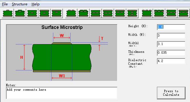
Generally speaking, the influence factors of PCB impedance are signal line width W, signal line thickness T, dielectric layer thickness h and dielectric constant ε R. Generally speaking, impedance is inversely proportional to dielectric constant, directly proportional to dielectric layer thickness, inversely proportional to linewidth, and inversely proportional to copper thickness.
Impedance calculation formula:
Z0=87/SQRT(εr+1.41)×ln[(5.98h)/(0.8w+t)]
Z0: Characteristic impedance of printed wire
εr: Dielectric constant of insulating materials
H: Medium thickness between printed wire and reference plane
H: Width of wire
H: Thickness of wire
With the upgrading of customer’s products, it is gradually developing towards intelligent direction, so the requirements for
impedance PCB board are becoming more and more strict, which also promotes the constant maturity of our impedance design technology.

