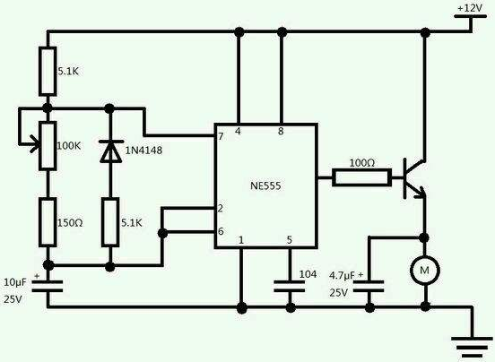
PWM is the abbreviation of "pulse width modulation". It is a very effective technology to control analog circuit by digital output of microprocessor. It is widely used in many fields from measurement, communication to power control and transformation.
Most of the control signals in the model aircraft are PWM signals, such as Futaba, Jr and so on.
The transmitter gives a series of pulses to the receiver. For example, the basic pulse width is 100ms. When the pulse width of the transmitter is increased to 150ms, the receiver will control the steering gear to rotate forward. When the transmitted pulse width is reduced to 50ms, for example, the receiver will control the reverse rotation of the steering gear.
PWM principle:
With the development of
PCB electronic technology, a variety of PWM technologies have appeared, including: phase voltage control PWM, pulse width PWM, random PWM, SPWM, line voltage control PWM, etc. the pulse width PWM method used in the intelligent charger of Ni MH battery takes each pulse train with the same pulse width as PWM waveform, and can adjust the frequency and change the pulse width by changing the period of the pulse train Or the duty cycle can be adjusted, and the voltage and frequency can be changed harmoniously by using appropriate control method. The charging current can be controlled by adjusting the cycle and duty cycle of PWM.
The value of analog signal can be changed continuously, and the resolution of time and amplitude is not limited. 9V battery is a kind of analog device, because its output voltage is not exactly equal to 9V, but changes with time, and any real value can be taken. Similarly, the current absorbed from the battery is not limited to a set of possible values. The difference between analog signal and digital signal is that the value of the latter usually only belongs to the pre-determined set of possible values, such as {0V, 5V}.
Analog voltage and current can be directly used for control, such as the volume control of car radio. In a simple analog radio, the volume knob is connected to a variable resistor. When you turn the knob, the resistance value increases or decreases; the current flowing through the resistance increases or decreases, thus changing the current value of the driving loudspeaker, making the volume increase or decrease accordingly. Like a radio, the output of an analog circuit is linearly proportional to its input.
Although analog control may seem intuitive and simple, it is not always very economical or feasible. One of them is that analog circuits are prone to drift over time and therefore difficult to adjust. The sophisticated analog circuits that can solve this problem can be very large, bulky (such as old home stereo) and expensive. The power consumption of analog circuit is proportional to the product of voltage and current at both ends of the working element. Analog circuits may also be sensitive to noise, and any disturbance or noise will definitely change the current value.
By controlling the analog circuit in digital way, the cost and power consumption of the system can be greatly reduced. In addition, many microcontrollers and DSPs have included PWM controllers on the chip, which makes the implementation of digital control easier.
To put it simply, for example, if you have a 5V power supply, to control the brightness of a lamp, there is a traditional way, which is to connect an adjustable resistor in series. If you change the resistance, the brightness of the lamp will change.
Another way is PWM adjustment. Instead of series resistance, a switch is connected in series. Suppose that within 1 second, there is 0.5 second time switch on and 0.5 second off, then the light will be on for 0.5 seconds and off for 0.5 seconds. If this continues, the lights will flash. If you turn the frequency up a little, for example, 1 ms, 0.5 ms on, 0.5 ms off, then the flashing frequency of the lamp is very high. We know that if the flicker frequency exceeds a certain value, the human eye will not feel it. So, at this time, you can't see the light flashing, only see the brightness of the light is only half of the original. Similarly, if within 1 millisecond, 0.1 millisecond on and 0.9 millisecond off, the brightness of the lamp will be only one tenth of its original brightness. This is the basic principle of PWM. The reason is so simple. There are several kinds of PWM. Generally speaking, they keep a certain voltage or current unchanged, but change the on and off time in a certain period. This is equivalent to keeping on but changing the voltage or current.
This PWM control method is very convenient in digital control circuit. This is because it is difficult for a computer to control an adjustable resistor, which also has the inherent instability of analog circuits.

